Datasheet
Cadence PCell Designer
Visual programming tool for Virtuoso PCell developers
Parameterized cells (PCells) are key elements used in analog and mixed-signal designs for increased flexibility and productivity of layout and schematic implementation. The development and maintenance of PCell libraries typically requires device knowledge and programming expertise. Cadence PCell Designer combines the ease of use of a graphical user interface (GUI) with a powerful object-oriented architecture for creation of reusable PCell classes and libraries reducing development efforts from multiple weeks to several days.
Overview
PCell Development Challenges
Development and maintenance of PCell libraries requires dedicated resources with the right skills profile. There are multiple requirements, in terms of complexity, technology rule agnosticism, performance, and maintainability. Advanced FinFET nodes are particularly challenging due to the complexity of both devices and rules.
These requirements are typically addressed by programming PCells in SKILL code. Management of code databases, including their maintenance, reuse, and applicability across technology nodes is one of today’s problems. Cadence PCell Designer is the modern, object-oriented, graphical PCell development environment designed to address these challenges.
Cadence PCell Designer Overview
Cadence PCell Designer targets PDK developers, layout engineers, and schematic designers who understand their device requirements. It provides an intuitive GUI within the Cadence Virtuoso Layout Suite and Virtuoso Schematic Editor to develop and debug PCells. Programming skills are not required. However, programmers can interact at a SKILL/SKILL++ level, if desired.
The result of the designed layout, schematic, or symbol PCell is shown in a PCell rendering window in real time. No compilation is required, nor is it necessary to leave the tool. Powerful debugging mechanisms allow a stepwise execution of the PCell. Compared to code-based debuggers, the higher level of abstraction gives superior debugging capabilities while maintaining full control on how the PCell is built. All PCell building commands are managed from the main GUI.
Develop Your PCell(s)
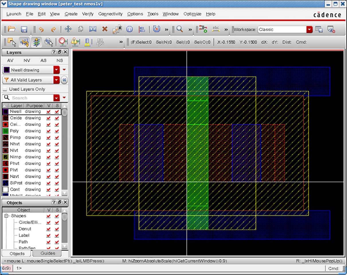
Draw shapes
Define shapes that belong to a device in your Virtuoso Layout Schematic or Symbol Editor. Alternatively use any OpenAccess view, an existing SKILL PCell, or a GDS-imported layout database as a starting point.
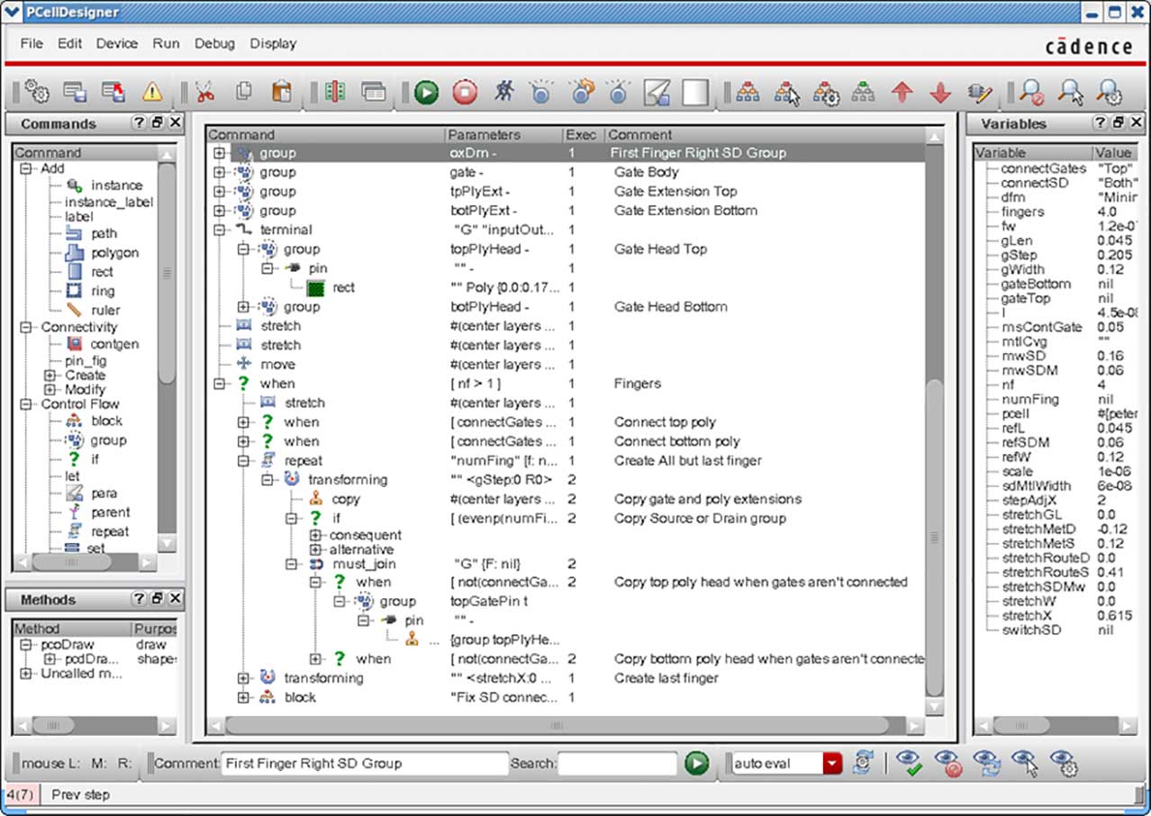
Build the PCell
Import the shapes into the Cadence PCell Designer main window and apply commands. These commands control the shape modifications, dependencies between shapes and layers, stretching, repetitions, pitches, contact creation, connectivity, etc. Commands may be controlled by both CDF and additional parameters. Instead of typing, you can use rulers and apply values directly to the building commands.
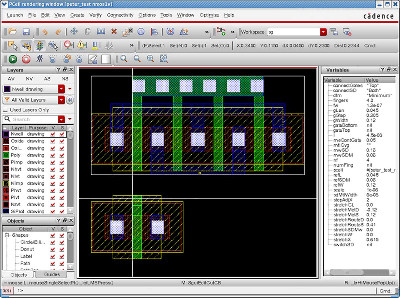
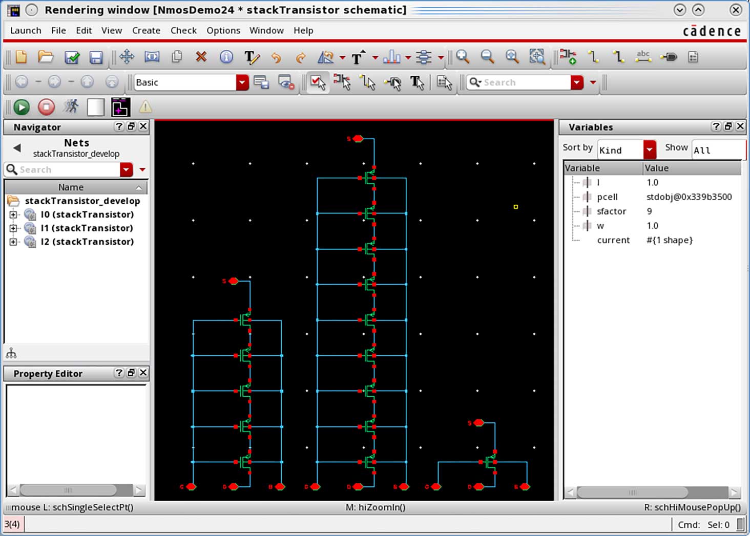
Validate PCell variants
Check the results in the PCell rendering window. A stepwise debugger allows you to view the effect of each command on the PCell. Instantiate as many PCell variants as needed to check the results visually and perform DRC checks by, for example, using iPVS within the Virtuoso environment.
Deploy PCell library
The final PCell library is a standalone library ready for use in the Virtuoso environment without a Cadence PCell Designer license.
Benefits
-
 Modern object-oriented capabilities in a GUI environment
 - Easy to learn
- No specific programming knowledge required
- Real-time PCell rendering window
- Re-use of class libraries for device families and across technology nodes
- Built-in debugger
- Powerful command library, clear structure and sequence, easy to maintain and handoff
- Significant reduction of PCell development time
- Enables collaboration of team of engineers and reduced PCell library maintenance effort
Features
- Full support of SKILL and SKILL++, including object-oriented programming styles
- Technology rules taken may be directly from the technology library; additional rules or overrides can be specified
- Comprehensive set of commands for shape manipulation, contact/via generation, connectivity, intra-device-level routing functionality, etc.
- Ability to define device classes and to be used in an object-oriented hierarchical manner
- Possibility to combine individual commands into methods for re-use
- Supports relative geometry for ease of creation of schematic and symbol PCells
- Switch display between command sequence or generated SKILL code
- Cross-reference and highlight between selected shapes in shapes window, PCell rendering window, and commands
- Supports hierarchical PCell instantiation
- Export complete, ready-to-use PCell library
Supported PCell Features
- Basic shape commands, including stretch, repeat, and copy
- Complex shape creation commands for inductors, power devices, etc.
- Advanced editing commands, including follow shape, follow path, modify corners, and geometry queries
- Virtuoso Layout Suite XL connectivity auto-abutment
- Hierarchical PCell modules
- Derive PCell from templates
- Base PCell on existing CDF or create CDF
Object-Oriented Features
Pcells are objects
- Define templates (classes)
- Define variants by deriving from templates (subclasses)
Create complex devices by placing several PCells
- Place several sub-instances
- Configure instances based on parent parameters
- Create extra geometry (for example routing)
Define behavior by commands (methods)
- Re-use behavior by putting commands in mixin classes
- Add or remove geometry (for example, add guard ring)
- Can create appCells (Application Cells) from commands to automate editing layout without writing SKILL code
Supported Design Environment and Tool Versions
- Fully integrated within Virtuoso platform
- IC 6.1.7 or later and ICADV 12.3 or later versions