Brochure
Dual-Role Device Controller IP for USB 3.1
Overview
Overview
Today’s Universal Serial Bus (USB) IP meets the demands of PC and mobile products for energy efficiency and higher perfor-mance. Cadence understands these technical challenges and offers the Dual-Role Device Controller IP for USB 3.1.
Certified for compliance with USB 3.1 Specification v1.0, and xHCI Specification v1.0, the Cadence Dual-Role Device Controller IP for USB 3.1 operates in SuperSpeedPlus (10Gbps), SuperSpeed (5Gbps), High-Speed (480Mbps), Full-Speed (12Mbps), and Low-Speed (1.5Mbps) modes. The USB 3.1 PHY interface complies with the PHY interface for the PCIe and USB 3.1 architectures (PIPE) Specification v3.2, while the USB 2.0 PHY interface complies with UTMI+ Specification, Revision 1.0.
Combined with Cadence USB PHY IP for USB Type-C designs, the Cadence Dual-Role Device Controller IP for USB 3.1 provides a complete solution for USB applications that will make use of the new, flexible, USB Type-C connector.
The Controller IP is silicon-proven, and has been extensively validated with multiple hardware platforms. The Cadence Dual-Role Device Controller IP for USB 3.1 is part of the compre-hensive Cadence Design IP portfolio comprised of interface, memory, analog, and system and peripheral IP.
Benefits
-
 Complete hardware and software solution—less time spent on application development
 - High level of configurability—better fit for application needs
- Industry-standard interfaces—simple system integration
Key Features
- Compliant with the following specifications: USB 3.1, USB 2.0, and xHCI 1.1
- PHY interface support with 32-bit PIPE, and 8-bit UTMI+ interface
- Arm AMBA 4 AXI initiator interface with 128-bit data and 64-bit address
- Full Link Power Management (U0, U1, U2, and U3) with LFPS and power/clock gating support
- AMBA APB4 responder interface with 32-bit data and address
- Hardware selectable dual mode operation without any software interaction
- SuperSpeedPlus (10Gbps), SuperSpeed (5Gbps), High-Speed (480Mbps), Full-Speed (12Mbps), and Low-Speed (1.5Mbps) operation
- Low gatecount implementation reuses same logic resource for Host and Device modes based on Intel xHCI specification
Product Details
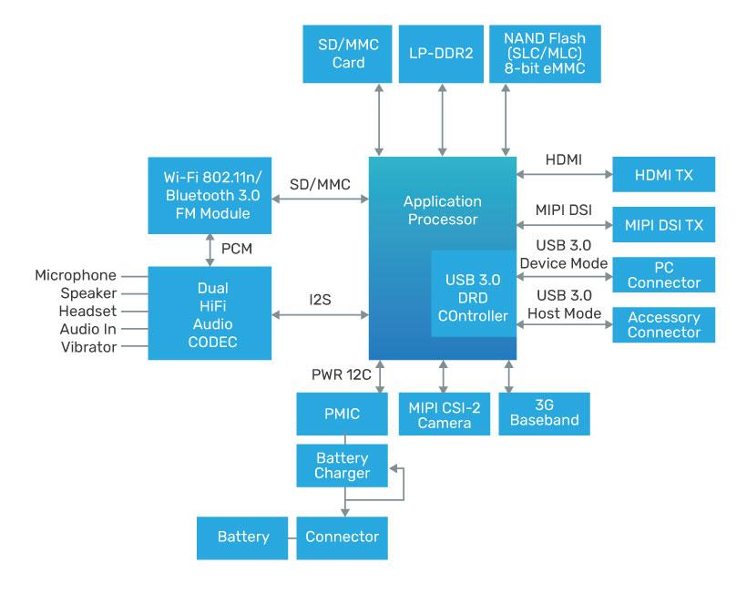
The Cadence Dual-Role Device (DRD) Controller IP for USB 3.1 implements the USB standard to manage connections for all types of USB applications, including but not limited to, mass storage, video, audio, communication, and vendor-specific applications.
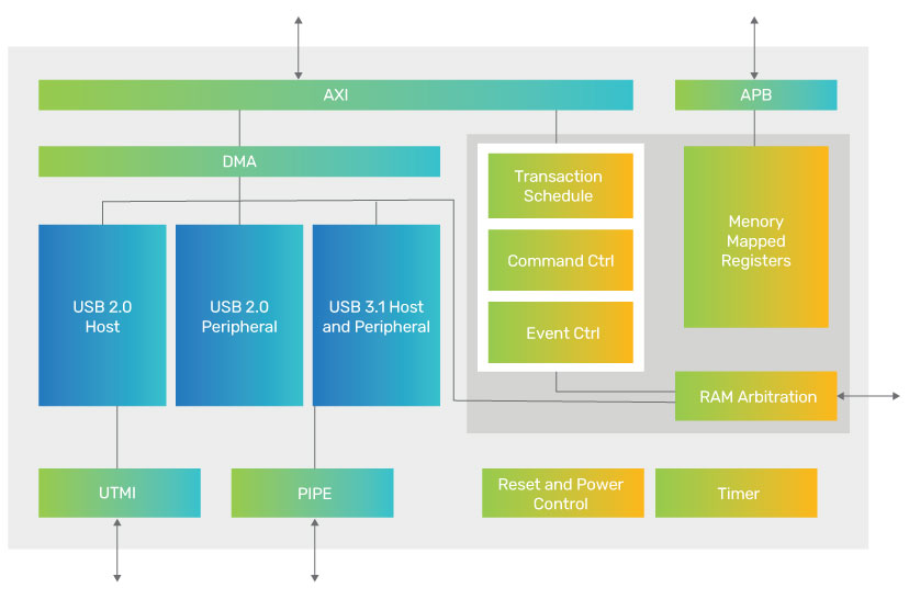
AXI Initiator Interface
The AXI Initiator Interface is designed to integrate to an application specific memory controller for providing operational data to the Cadence USB 3.1 controller. This interface is used to gain access to application memory. DMA is used to access data structures and related information during normal operation.
APB4 Responder Interface
The APB Controller interface allows for S/W programmability of the Cadence USB 3.1 controller, including DRD, Host and Device controller logic. It also provides control and operation status information to driver software.
System Power Management Interface
When the application desires to employ Power Management, these signals provide an interface to the System Clock Controller to enable dynamic power saving states.
Interrupt Interface
This interface provides interrupt signals to the external CPU for various events detected within the Cadence USB 3.1, including DRD, Host and Peripheral-defined interrupts.
MSI Interface is included in the Cadence USB 3.1 to support application interrupts. If enabled, the core will generate 32-bit write operation at the AXI Initiator Interface instead of using interrupt lines. The address and value of the write is controlled by xHCI Extended Message Interrupt Capability.
Mode Select Interface
This interface allows an external hardware mechanism to determine the default mode of operation, without the need for software to program the DRD logic within the Cadence USB 3.1. This allows an alternative protocol to perform the role negotiation or for the mode to be hardware strapped.
On-Chip Memory Interface
SPRAM memory modules are used to store information about Slot/EP state and as a scratchpad memory for the Cadence USB 3.1. They are used also in USB2.0 Host Port to implement the USB 2.0 SPLIT protocol. DPRAM memory is used for USB transfers buffering and clock domains synchronization.
Availability
The Cadence USB 3.1 Dual-Role Device Controller is available with various configurations.
Related Products
- VIP IP for USB 3.1
- PHY IP for USB 3.1/2.0
- 10Gbps Multi-Link Multi-Protocol SerDes IP
Deliverables
- Synthesizable RTL
- Testbench
- Synthesis and simulation support files
- Documentation
For more information, visit designip