Datasheet
Microwave Office / VSS E-Series RF Solutions
Circuit, system, and EM/thermal simulation for RF to mmWave product development
Cadence Microwave Office circuit design software is used by leading manufacturers to develop high-frequency electronics. RF-aware layout, high-frequency models, and a powerful harmonic balance (HB) simulator ensure accurate and fast simulation results for first-pass success. The intuitive interface, innovative design automation, and design-assist features promote optimum engineering productivity and accelerate the development of RF/microwave IP across monolithic microwave IC (MMIC), RF PCB, and module technologies as standalone components or integrated within complex multi-technology systems.
Overview
Overview
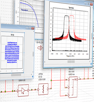
Cadence Visual System Simulator (VSS software) RF/ wireless communications and radar system design software provides link budget and spurious heritage analysis with end-to-end time-domain and circuit-envelope simulations. With VSS software, wireless design teams apply behavioral, impedance-aware RF models and baseband signal processing blocks to develop and optimize system architectures and determine component specifications for the best overall performance. Users can simulate system metrics such as adjacent channel power ratio (ACPR), bit-error rate (BER), and error vector magnitude (EVM) with pre-configured and user-defined virtual testbenches, as well as identify the source of spurious products and other system impairments.
Both products are fully integrated within the Cadence AWR Design Environment platform to provide RF/microwave engineers with high-frequency circuit, system, multiphysics (EM and thermal) in-design analysis, and implementation workflows to develop physically realizable electronics ready for manufacturing. The new Microwave Office E-Series includes the interface to Cadence’s AXIEM 3D Planar EM Analysis, and EMX Planar 3D Solver EM, Clarity 3D Solver, and Celsius Thermal Solver technologies as part of the base product. In addition, design management (version control), connectivity checking, sub-circuit simulation caching (APLAC turbo), and Linux server farm support are now standard features to accelerate RF product development across design teams and promote first-time success.
Benefits
The new E-Series includes:
-
 Microwave Office
- In-design analysis interface (IDAi) for Cadence’s Planar EM and 3D EM/thermal solver technologies provide schematic-driven extraction in the base Microwave Office products. Solvers can be added with EM tokens or Clarity, Celsius, or EMX licenses
- Group design management and revision control
- Connectivity checking detects shorts or opens in circuits by determining the connectivity in a layout
- Sub-circuit caching significantly reduces simulation run times for large, hierarchical designs
- Run AXIEM (planar EM) or Analyst (legacy AWR 3D FEM) simulations on a remote Linux cluster
-
- VSS Software
- Frequency (budget and spur heritage) and time domain (BER, EVM, constellation plots, eye diagrams) analysis from the same system blocks, now with included 5G communication standard libraries
- Phased array synthesis and array/feed network schematic generation
-
Configurations to Meet Your Design Focus
Linear
MWO126E supports the design of RF passive components such as filters, couplers, and attenuators, as well as active devices operating under small-signal (ac) conditions, such as low noise and buffer amplifiers. All E-Series Microwave Office products include synchronous schematic / layout editors, 2D/3D viewer, comprehensive libraries of high-frequency distributed transmission models, and surface-mount vendor component RF models with footprints, measurement-based simulations, and RF plotting (Smith charts, polar and rectangular, antenna plots, etc.). The linear configuration supports the simulation of S-parameters (Y/Z/H/ABCD), small-signal gain, linear stability, noise figure, return loss/ voltage standing wave radio (VSWR), and more, as well as real-time tuning, optimization, and yield analysis.
PCB
MWO226E enables linear and nonlinear RF circuit design with the robust APLAC harmonic-balance (HB) simulator and its powerful multi-rate HB, transient-assisted HB, and time-variant (circuit envelope) simulation engine, supporting the analysis of large-scale and highly nonlinear RF/microwave circuits, such as power amplifiers and mixers (frequency converters). State-of-the-art load-pull analysis with harmonic and video-band tuning generate performance contours, including available output power, gain, power-added efficiency (PAE), two-tone intermodulation distortion, and other key amplifier metrics used in the development of input/output matching circuits for optimum performance.
MMIC
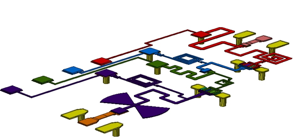
MWO228E offers a front-to-back monolithic microwave integrated circuit (MMIC) design flow with an innovative user interface and complete integration of design entry, simulation, and physical design tools that enhances engineering productivity and ensures first-pass success with PDKs from a wide range of gallium arsenide (GaAs), gallium nitride (GaN), silicon germanium (SiGe), and CMOS foundry partners. The hierarchical framework supports the simulation of diverse MMIC, RFIC, and PCB processes, multi-layer interconnects, embedded passives, and surface-mounted mini-devices found within multi-chip RF modules.
System
VSS350E allows design teams to conceptualize and rapidly implement virtual 5G/6G and IoT communication and radar/ electronic warfare (EW) systems, investigate new architectures, and study individual components or overall system performance. It also helps design RF-aware systems and perform rigorous link budget design or spurious heritage analysis with RF/ microwave behavioral models that incorporate linear and nonlinear performance metrics as well as terminal impedances that lead to power loss due to component-to-component impedance mismatch. Combine with signal processing blocks to cover end-to-end system performance and communication testbenches for co-simulation with Microwave Office and/or Virtuoso IP.
With MWO126E, MWO226E, and MWO228E
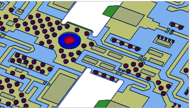
In-Design Analysis Interface
In-design electromagnetic (EM) and thermal analyses are increasingly critical to successful RF and microwave product development. Frequency requirements, circuit complexity, circuit density, and size constraints drive design requirements that benefit from concurrency between circuit simulation and layout analysis. Circuit/system and EM co-simulation provide first-pass design success with a complete analysis of high-frequency electronics with interconnecting transmission lines and embedded active and distributed passive elements. The in-design analysis interface, now a standard feature in Microwave Office E-Series, provides a flexible in-design analysis solution with a standalone EM extraction workflow for Microwave Office developed PCB or MMIC IP or EM verification of imported Allegro IP or from standard PCB formats such as DXF, Gerber, ODB++, and IPC-2581 using the PCB import wizard. EM and thermal analyses are available with the addition of EM tokens or Cadence multiphysics analysis tools such as Clarity 3D Solver or Celsius Thermal Solver, described below.
Microwave Office E-Series also includes the automated circuit extraction (ACE) interconnect analysis tool, which converts PCB layout into high-frequency netlist-based representations of complex interconnects, including crossovers, vias, and multilayer coupled-line models. ACE technology allows engineers to accelerate their design starts with an initial representation of electrical performance from physical design before committing to planar and/or 3D EM analysis.
Design Management
The AWR Design Environment platform supports the integration of version control software to effectively manage group design projects, allowing data management of complex, multi-function designs on different technologies. Revision control software records and manages control documents/ data file(s) and stores them in a central database or repository. Commands instruct the software on managing the target file(s) in a repository, and the commands are added to the file history. The software manages and allows access to the file history and database of all files stored within. For group design, version control software file management prevents unintentional file overwrites when multiple users edit the same file in the version control database or central repository— support for multiple version control software vendors, including Apache Subversion, Perforce, and Cliosoft.
Connectivity Checking
The Connectivity Checker detects shorts or opens in circuits by determining the connectivity in a layout using “Connectivity Rules” and layout shapes. This connectivity is compared with the schematic connectivity to show where there are errors. Errors are listed in the Errors Window and are easy to navigate. The Connectivity Highlight function highlights the shapes connected in the layout using the “Connectivity Rules” in one color. It does not check for open or short errors. The Connectivity Checker only analyzes DC connectivity, not the RF, and is not a replacement for layout versus schematic (LVS). Use this feature together with rat lines checking in “Design Rule Checking (DRC) ” to make the design as clean as possible before signing off with an LVS tool.
Sub-Circuit Caching
Sub-circuit caching reduces the simulation run time in designs containing linear portions that do not change but are time-consuming to compute. Microwave Office software uses the sub-circuit hierarchy when searching for cache candidates and stores its Y parameters and noise parameters on disc. For subsequent simulations, the Y-parameter data of unchanged sub-circuits are read from the disc cache. Sub-circuit caching can speed up the simulation in various scenarios: when there are multiple instances of the same sub-circuit in the same top-level simulation, when there are multiple top-level simulations in the same project using the same schematic as a sub-circuit, or when re-opening a project that has previously stored sub-circuit cache data.
Run Remote EM Simulations on a Linux Cluster
Remote computing allows you to set up a simulation on a local computer but simulate the structure or schematic on a different computer. By setting up dedicated, remote computers for resource-intensive simulations, you can use local computers for other work or smaller simulations. With Microwave Office E-Series, you can now run AXIEM and Analyst simulations from the AWR Design Environment platform on a remote Linux cluster.
With VSS350E
5G/Radar Library
The 5G/Radar library offers easy-to-configure signal sources and receivers that can be used to evaluate RF components and/or RF links used in radar and 5G system-level measurements. Preconfigured measurements for 5G NR transmitter components include complementary cumulative distribution function (CCDF), AM to AM/PM, spectrum, EVM, ACPR, IQ constellation, and more. 5G NR receiver simulation sensitivity measurements include BER, block error rate (BLER), and throughput. For radar applications, the library offers radar signal generation, radar-specific target and propagation modeling, and radar signal processing capabilities, including moving target indicator (MTI), moving target detector (MTD), and constant false-alarm rate calculator (CFAR).
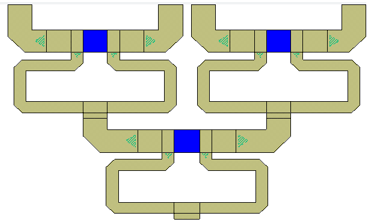
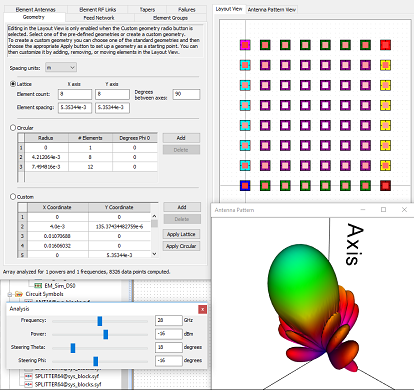
Phased Array Systems
The phased array generator wizard enables designers to interactively design a phased array antenna and then generate schematics or system diagrams that represent the design. Quickly configure planar phased array or multiple-in-multiple-out (MIMO) array systems, interactively modify designs to achieve the desired behavior, and generate system diagrams and/or circuit schematics and electromagnetic (EM) structures for further, more rigorous analysis. The wizard supports interactive specification of the layout, feed network settings, element antenna and RF link settings, gain tapers, and element failures. Simulate critical antenna performance in phased arrays with a reconfigurable model supporting thousands of radiating elements based on measured or simulated antenna data for the development of beamforming algorithms, evaluation of hardware impairments, and RF link analysis.
Add-On Options
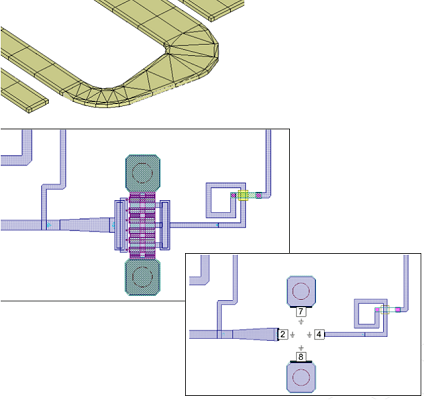
AXIEM Planar EM and Analyst (legacy AWR 3D FEM)
Add a single EM token (TOK120) to enable the AXIEM 3D proprietary full-wave planar, open-boundary method-of- moments (MoM) fast-solver technology to readily analyze distributed PCB components, transmission lines, and layer- to-layer PCB interconnects such as vias. Designers can extract S-parameters directly within their PCB design and visualize fields/currents to identify parasitic coupling and resonances. The AXIEM hybrid-element, conformal surface meshing of planar 3D structures ensures fast and accurate results. Add another TOK120 to enable Analyst 3D FEM EM simulator for arbitrary 3D structures such as wire bonds, ball-grid arrays, and RF connectors. Simulate near- and far-field radiation patterns, surface current, gain, bandwidth, and return loss for planar, 3D, and phased array antennas.
Clarity 3D FEM Solver
The Microwave Office E-Series now works directly (no additional add-ons required) with the Clarity 3D Solver, our 3D EM simulation software tool for designing critical interconnects for PCBs, IC packages, and System-on-IC (SoIC) designs. Cadence’s industry-leading distributed multiprocessing technology in the Clarity 3D Solver delivers virtually unlimited capacity and a 10X speed improvement required to efficiently address larger and more complex structures, creating highly accurate S-parameter models for use in high-frequency RF/microwave applications and electromagnetic compliance (EMC) analysis.
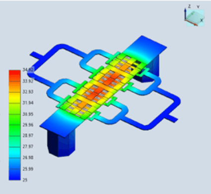
Celsius Thermal Solver
Microwave Office E-Series pairs with Celsius Thermal Solver to deliver a complete electrothermal co-simulation technology for monolithic microwave ICs (MMICs), IC packages, RF PCBs, modules, and microwave/RF systems. The Celsius Thermal Solver is integrated within the Cadence AWR Design Environment platform, providing ready access to high-capacity electrothermal analysis for design verification and signoff of large, densely populated RF/microwave systems and high-power amplifiers using layout, stack-up, and power dissipation information already available in your Microwave Office design.
EMX 3D Planar EM for On-Chip Silicon Design/Analysis
Microwave Office E-Series also integrates EMX Planar 3D Solver, offering the fastest EM simulator for silicon IC passive devices such as inductors, transformers, and BALUNs. Based on fast multipole methods (FMMs) and volume mesh formulation for conductors, the EMX solver provides unmatched speed and the highest-in-class accuracy from within Microwave Office software to support on-chip passive component characterization, silicon MMIC design, and detection of the parasitic coupling that directly impacts performance. The EMX solver ties into the process technology in the form of foundry-certified process design kits (PDKs) as well as a foundry-certified EM simulation technology.
Advanced Circuit Simulation – Circuit Envelope, Time Domain, and Nonlinear Stability
The advanced circuit simulation add-on option (ASK300) in Microwave Office expands the RF nonlinear simulations offered by the APLAC multi-rate HB engine to include circuit envelope and time domain analyses. As a part of this capability, engineers can simulate modulated signals using IQ data and measure the time domain waveforms around a carrier or look at the corresponding spectrums. Circuit envelope simulation can be used to simulate circuits sourced with modulated signals. The envelope analysis is based on harmonic balance but includes additional time integration parts from dynamic models. This option also includes fast and rigorous nonlinear stability analysis for RF power amplifiers.
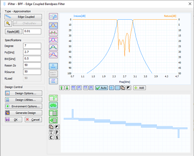
Synthesis - Filters and Impedance-Matching Networks
The Microwave Office iFilter integrated filter synthesis wizard enables filter designers to accelerate design starts with a powerful synthesis of lumped- and distributed-filter types, and supports the export of the resulting circuit topologies directly into the Microwave Office software for further refinement, optimization, EM verification, and physical design. The network synthesis wizard works by automatically creating optimized two-port impedance-matching networks. The user specifies the maximum number of sections and types of components to search— the evolutionary algorithm then finds the best circuit topologies and optimizes component parameter values. The network synthesis tool supports networks synthesized with components from the Microwave Office vendor library and foundry-authorized process design kits (PDKs).
VSESIM-VSS – Link to R&S Software Products and Test Equipment
The VSESIM-VSS from Rohde & Schwarz (R&S) connects all the required standards and modules of its software products: WinIQSim2, VSE, Direct DPD and R&SVSE with Cadence VSS software supporting co-simulation between VSS software and R&S SW. This link allows VSS software users to replay signal sources created with R&S WinIQSim2 and used in R&S signal generators. R&S VSE can be used for demodulation and measurement of standard signals passed through VSS software or co-simulated with Microwave Office and/or Spectre netlist (Virtuoso IP). The direct DPD software implements a DPD algorithm that does not require prior knowledge of the device simulation model.
| Linear | PCB | MMIC | System | |
|---|---|---|---|---|
| PN | MWO126E | MWO226E | MWO228E | VSS350E |
| Key Features |
|
Linear +
|
PCB +
|
|
| Applications |
|
|
|
|
| Recommended Options |
|
|
|
|