Technical Brief
Timing-Aware Design Flow Using Hierarchical Metal Fill Database
Overview
Introduction
Metal fill is essential to maintain a constant metal thickness across the chip, but timing closure is becoming increasingly difficult at advanced nodes because parasitic capacitance variations affect timing. The conventional flow of generating metal fill externally after P&R, RC extraction, and timing checks requires many iterations and results in high design turnaround time (TAT). Cadence provides a metalfill-aware physical design environment that integrates Pegasus Verification System and Quantus Extraction Solution within the Innovus Implementation System. The features include Quantus extraction’s integrated virtual metal fil (IVMF), Pegasus verification’s signoff metal fill generation, Pegasus verification’s incremental metal fill/ Quantus extraction’s incremental RC extraction, and Pegasus verification’s metal fill removal around critical nets.
It is very critical for designers to implement the timingaware metal fill design flow early in the design process in order to significantly reduce TAT in the total flow and to shorten the design cycle time. This technical brief discusses the inherent challenges in the conventional design flows and the mitigation strategy in a metal-fillaware physical environment.
Analysis
In layout design, the variation of wiring film thickness caused by the coarseness and denseness of the metal layer can be a bottleneck in the manufacturing process. It is time to consider a novel approach, to chip design that considers metal fill in-design.
The Cadence chemical and mechanical polishing (CMP) predictor (CCP), predicts the CMP variations and their potential impact on the design for the entire stack. The CCP also uses a highly accurate model-based approach to find potential areas in the design in order to increase the thickness variation data into extraction tools, thus enabling better RC and timing analysis.
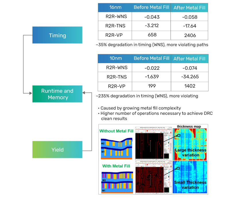
As shown in Figure 1, the thickness of the film without metal fill is uneven. However, with the addition of metal fill, the variation of film thickness is suppressed and flattened.
On the contrary, considering the characteristics of film thickness with circuit wiring, the metal fill is placed near the wiring, which increases the parasitic capacitance and causes timing degradation issues.
An Example
As shown in the table in Figure 1, when the metal fill is placed near the wiring, timing is degraded by 35% at the 16nm node, 235% at the 10nm node in some cases, and is further degraded at 7nm and 5nm.
The complexity of fill-related design has increased with the advancement in process nodes. In addition, the need to minimize the impact on timing, while ensuring uniform pattern occupancy, has increased.
Issues with Conventional Design Flow
With design-rule complexity increasing with addition of recommended design rules, it is difficult for the conventional fill synthesis paradigms to cope. The conventional flow is used to perform timing optimization without considering metal fill in the physical design flow, see Figure 2.
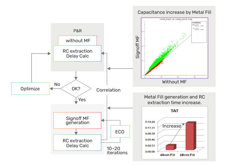
Subsequently, the signoff metal fills are inserted externally, away from the place and route (P&R). Even if a scale factor is applied to perform RC extraction, it is difficult to correlate the timing, for the timing is deteriorated by metal fill insertion, and this requires many iterations to close the timing. In addition, as the amount of metal fill in technology nodes increases, the fill generation time and RC extraction time increases—leading to a reduction in design cycle TAT.
Therefore, in order to improve the design cycle TAT, it is not only important to reduce the number of iterations, but also critical to shorten the TAT per iteration.
Integration
While regular planarization is critical, metal fill can also negatively affect timing due to increased coupling capacitance in the nearby nets. So, it is paramount for the designer to consider the metal fill without impacting timingcritical nets. In order to overcome this shortcoming, the fill needs to be timing-aware, which is also needed when an engineering change order (ECO) arrives late in the design cycle—the ECOs make it indispensable for the designer to change the layout and fill around the affected area. Thus, it is imperative that the fill method should allow easy removal of and re-insertion without violating timings of the nearby nets.
Considering the shortcomings in timing and signoff, an ideal metal fill must have the following facets:
-
 Faster TAT and timing-aware
 - Accurate signoff
- Reduce time required around ECO/timing loops and run virtual metal fill earlier in design during post-route optimization stage
- Support a hierarchical design to enable higher productivity, ease of inserting metal fill
Innovus implementation considers the impact of the metal fill and provides an end-end full-flow layout design environment. The flow aims at reducing TAT of the total design by considering in-design signoff metal fill—which also enables designers to implement signoff quality by making necessary corrections within the physical design environment. This flow not only reduces the number of iterations in a single design cycle iteration TAT, but also reduces the number of individual iterations—significantly shortening the total design cycle time.
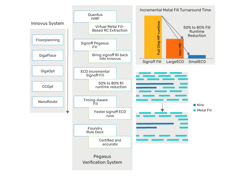
The timing-aware metal design flow, as shown in Figure 3, consists of four functions:
- Quantus extraction’s IVMF in Innovus implementation
- The Pegasus verification’s hierarchical metal fill (HMF) in Innovus implementation
- Pegasus verification’s incremental metal fill/incremental Quantus extraction’s RC extraction
- Pegasus verification’s metal fill removal around critical nets
In addition to the above, hierarchical fill database is built into Innovus implementation, which makes it easy and efficient to handle the post-fill data.
Quantus Extraction’s IVMF in Innovus Implementation
In order to extract RC with metal fill, both metal fill generation and RC extraction with metal fill are required.
An Example
As shown in Figure 4, the IVMF feature in Quantus extraction reduces TAT by setting up virtual metal fills and RC extraction.
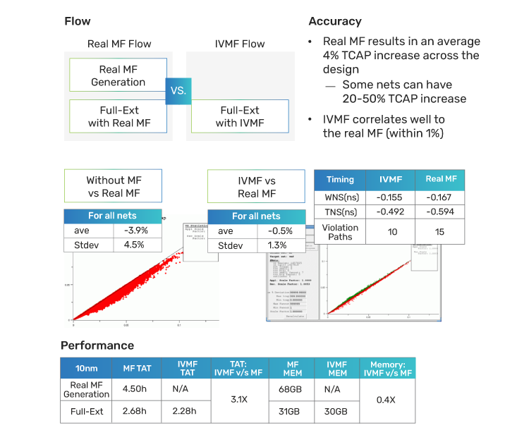
Also, as shown in the rightmost plot in Figure 4, the capacitance of the virtual metal fill and signoff metal fill are well correlated with each other, with a negligible variation in the 45-degree line. The timing analysis table shows that there are ten violation paths in the virtual metal fill and 15 violation paths in the signoff metal fill, which shows a good correlation.
The runtime examples show that TAT is 3X faster and memory is reduced by half when compared to a flow with metal fill. This increased TAT is beneficial if used early in the design flow, because it reduces the number of iterations for timing closure.
Pegasus Verification’s HMF in Innovus Implementation
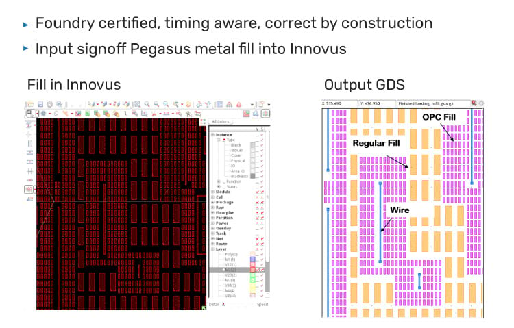
The Pegasus verification’s HMF is generated in Innovus implementation by running the command add_metal_fill_ signoff -fill using the foundry-provided Pegasus rule deck. The properties of the generated metal fill, such as FILLWIRE and FILLWIREOPC are set appropriately, and the subsequent flow can be handled in the same way as the normal metal fill pattern. For more details, see Figure 5.
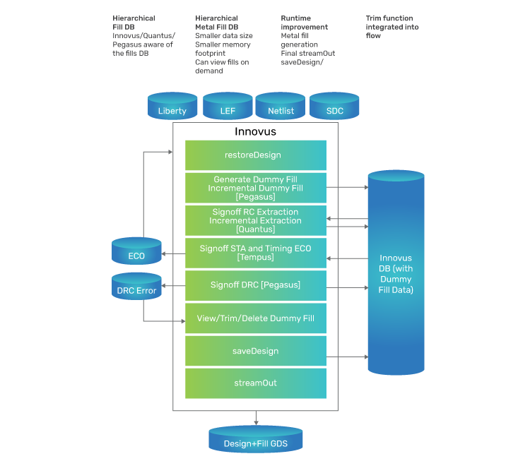
The Pegasus verification’s HMF flow stores generated metal fill data in the Innovus implementation database as a metal fill database—which gives access to the Innovus, Quantus, and Pegasus solutions, as deemed necessary to process metal fill requirements. For more details, see Figure 6.
The Pegasus verification’s HMF flow keeps the metal fill data hierarchy intact and reduces the size of the data by one-third, which is shown in the example section below.
An Example
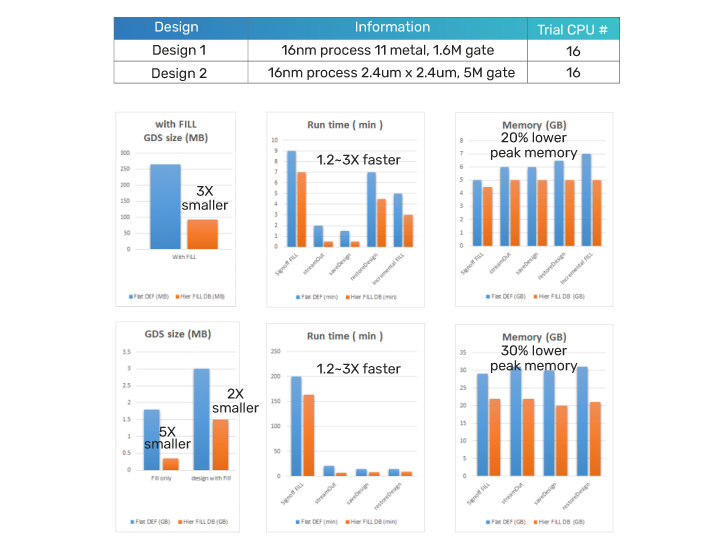
The hierarchical fill database is accessible by the Innovus, Quantus, and Pegasus solutions where applicable. This need-based access on an average improves TAT by 1.2X to 3X and memory by 20%, see Figure 7.
In the case of timing violations, it is necessary to perform an ECO and rewire, extract the RC with the updated metal fill, and then check the timing—all of which can be done within Innovus implementation.
Pegasus Verification’s Incremental Metal Fill/Incremental Quantus Extraction’s RC Extraction
Due to the escalating design size and complexity in advanced node design, each job takes longer to execute. So, incremental processing is required for various layout processes and tools to process only the newer fill changes. In addition, incremental processing functions are also important for metal fill to reduce TAT. This corresponds to the incremental dummy fill and extraction steps of the hierarchical fill database shown in Figure 6.
When the initial signoff metal fill generation, RC extraction, timing analysis, and ECO are performed, some wiring patterns disappear, while some new patterns are generated. The newly added wiring pattern will cause a DRC violation between the initial metal fill and may be required to be removed. So, it is also essential to add metal fill to the empty spaces of the disappearing patterns of wires.
As shown in Figure 8, the designer can achieve this in the Pegasus verification’s incremental metal fill generation by using the incremental command add_metal_fill_signoff -incremental, which is used to perform a sequence of operations.
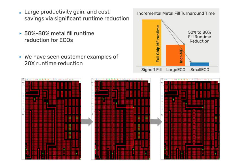
The Pegasus verification’s incremental metal fill feature satisfies the following requirements and significantly reduces TAT during iterations:
- The metal fill generation rules provided by the foundry can be applied as is
- The lesser the design changes, the lesser the execution time
- The accuracy and timing results are almost identical with and without the incremental function
Similarly, the RC extraction also performs incremental processing by checking not only net differences, but also metal fill differences. Even with incremental RC extraction, if the amount of change is small, RC extraction can be done in a shorter time, and processing time can be expected to be significantly reduced.
Pegasus Verification’s Metal Fill Removal Around Critical Nets
The metal fill removal around the critical net reduces the timing impact with keeping minimum density, thus enabling to correct timing violations while meeting the DRC density rules and CMP flattening criteria, which is achieved by subtracting a small amount of metal fill from the signoff metal fill. The trim command add_metal_fill_signoff -trim is used to trim the fills.
As shown in Figure 9, after the metal fill is generated, the critical net is detected by timing analysis and the metal fill around is removed.
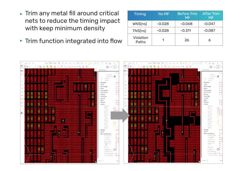
The user can define the critical net and the extent of metal fill removal from the net or Pegasus verification can automatically read through the Innovus and Tempus Timing Signoff reports. At advanced nodes, the effect of the parasitic capacitance of the upper and lower metal fills, as well as the metal fills of the same layer has been found to be significant. So, the option to remove the upper and lower layers as well has been built in. In the top-right table of Figure 9, the number of timing violations increased from one without metal fill to 26 with metal fill generation. However, it was reduced to six by removing the metal fill around the critical nets. Removing metal fills to improve timing will not help if it results in a density violation, so this command has a built-in -union_density option to set the minimum density desired for each layer.
Conclusion
Escalating design size and complexity, more complex DRC challenges are causing the physical verification TAT for the advanced nodes to explode. In order to reduce TAT in the total flow, it is critical for designers to implement the timing-aware metal fill design flow to significantly shorten the design cycle time.
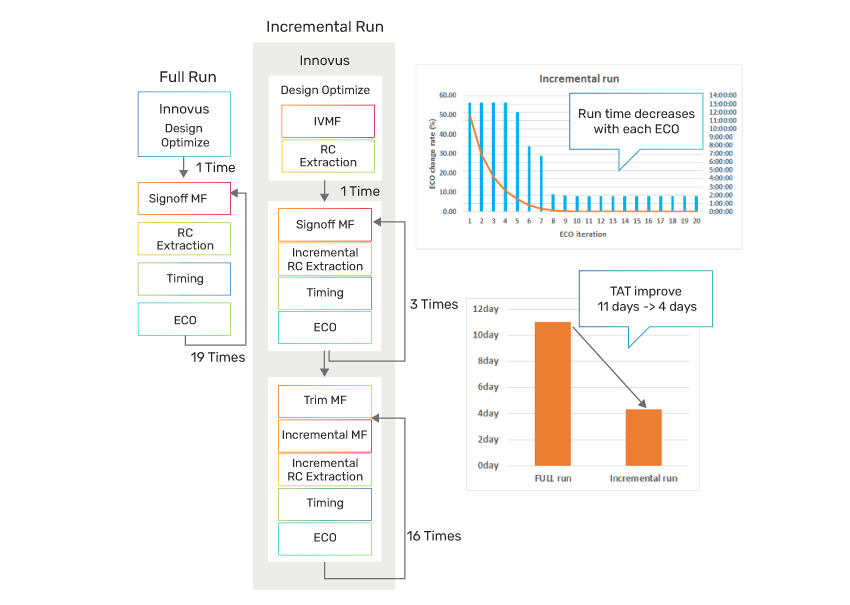
Figure 10 shows comparison of TAT per iteration with reference to no fill. With virtual metal fill, TAT is 1.2X more than that without metal fill and is 2.5X more with signoff metal fill. Depending on the size of the ECO, the time can be reduced to less than the TAT without metal fill by applying the incremental metal fill generation/incremental RC extraction function.
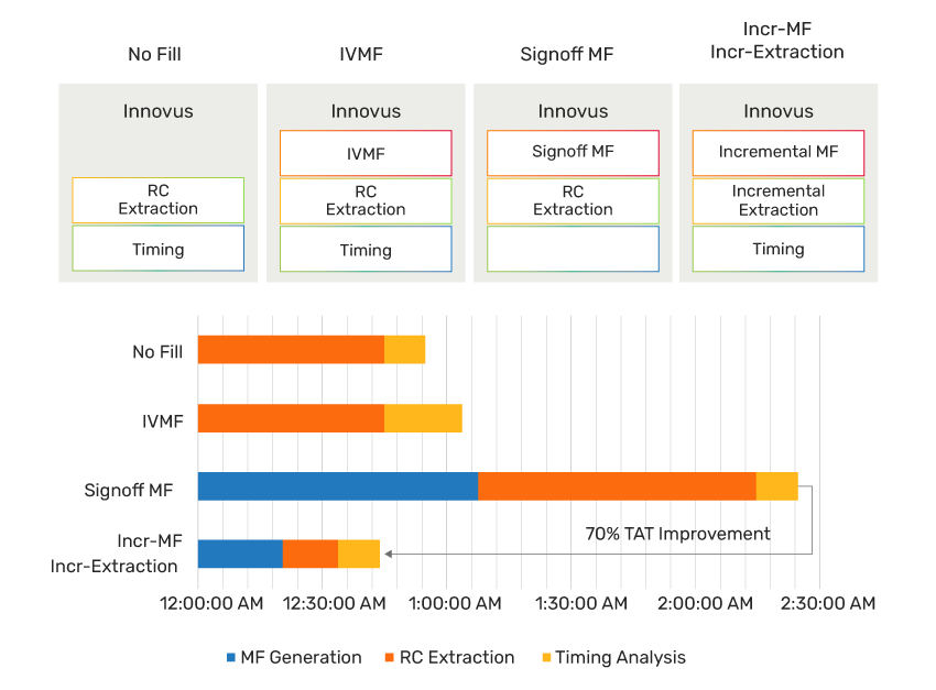
Figure 11 shows the estimated total TAT for the actual design based on a single iteration TAT, with a significant reduction in the total design cycle iteration TAT, from 11 days to 4 days. The number of iterations is assumed to be the same for both flows (20 in total), but in the timingaware metal fill design flow, the number of iterations itself can be expected to be reduced because of a smooth timing closure.