Product Overview
Cadence Janus NoC
Overview
Cadence NoC Architecture
The Cadence Janus Network on Chip (NoC) is a new highly configurable soft IP designed to speed up the system-on-chip (SoC) and full system design cycle by reducing some of the problems associated with large SoCs.
With many more processing nodes, as well as memory and I/O nodes designed into the SoC, the interconnect becomes a major design hurdle. Wiring congestion and wire loads introduce challenges to physical designs, specifically when routing large numbers of wires and meeting clock speed targets.
The Cadence Janus NoC addresses those challenges by employing multiple strategies:
-
 Packetization allows a reduction of the wire count
 - Significant reduction of the complexity of large crossbars by partitioning them into smaller ones
- Introduction of pipelining to links with heavy loads, allowing the NoC to operate faster
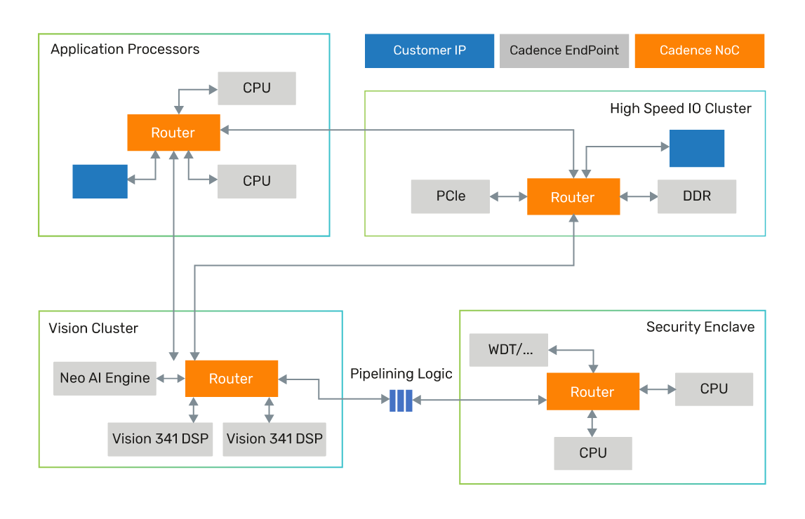
The diagram below shows the basic elements of the Cadence Janus NoC.
- Endpoints – The different working elements of the SoC, the processors, memory elements, I/O elements, and so on.
- Routing node – Cross bars that connect to endpoints and allow traffic to and from each endpoint. Routing nodes are connected between them to allow traffic from an endpoint connected to one routing node to another endpoint connected to another routing node.
- Reduced Design Complexity – The connection between the routing node and endpoints provides for clock domain crossing, clock gating, width matching, and an added pipeline, thus reducing the design complexity associated with managing them.
NoC Configuration and Generation
Consider a NoC with 30+ initiators and a similar number of targets, as well as five or even more routing nodes. Such a NoC means configuring:
- Width of AXI/AHB and APB links
- Pipeline stages on those links
- Width of links between the different routing nodes
- Pipeline stages between those links
- Clock domain crossings
- Buffering requirements for each possible egress and ingress ports of the crossbar switch, which is the heart of each routing node
- Address map, i.e., the address range for each target for every possible initiator that needs to access it
That is a lot!
Cadence has developed a state-of-the-art GUI configuration tool that allows users to drag and drop routing nodes, drag and drop Initiator Endpoint Adapter (IEA) and Target Endpoint Adapter (TEA), connect to those nodes, and then configure the different links based on that link type. Add to that a smart way of creating address maps, and the process becomes a matter of hours instead of days.
The GUI generates a text file, which is then used to generate the RTL, functional SystemC model, synthesis script, and regression tests. Need to modify? Easy. Need to use it as a baseline for the next generation? Easy.
Along with the RTL and models, the tool also generates a fully functional testbench with all necessary Verification IP (VIP) to allow the user to verify the NoC functionality and performance.
The snapshot below shows a NoC being designed using the Cadence Janus NoC’s design entry tool.
